
WORKSHOP & PROCESS
How we build a battery.
We follow one pack, a Razor 20S8P, from the first drawing to the finished case. Most photos are of that pack, taken in our workshop while we built and tested it. Where a step wasn’t photographed on the Razor, the caption says so.
RAZOR 20S8P · 160 CELLS · TWO SLOPED 10S8P MODULES · BUILT APRIL 2026
01 · DESIGN
Drawn in DogeTune Builder
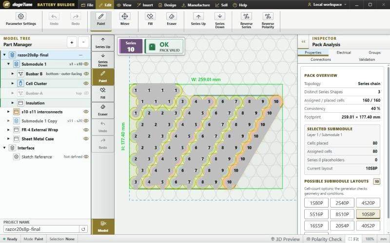
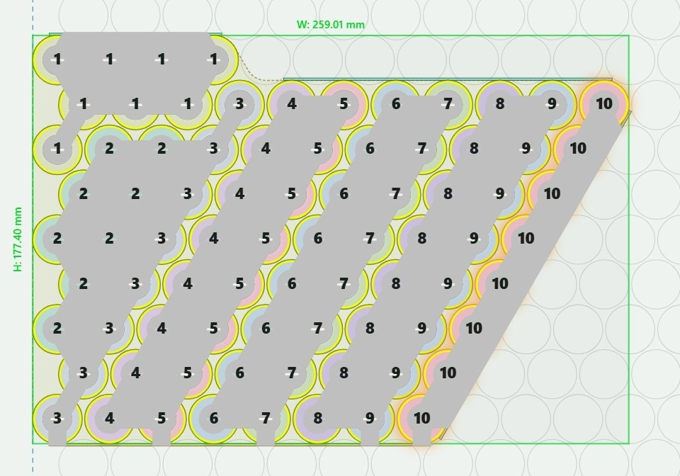
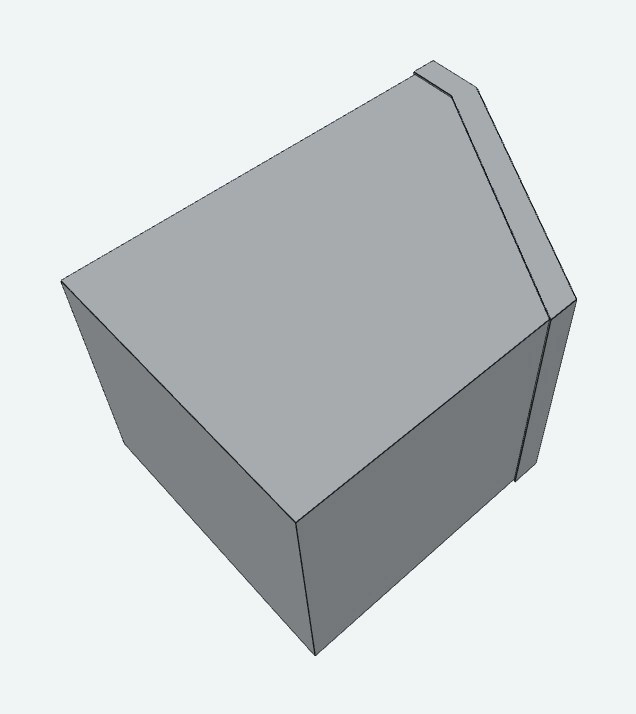
The Razor’s battery space is a box with a sloped end, so a plain block of cells won’t fit. In DogeTune Builder, our own battery design software, we drew two 10S8P modules that follow the slope, then joined them into one 20S8P pack.
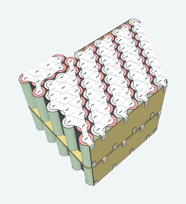
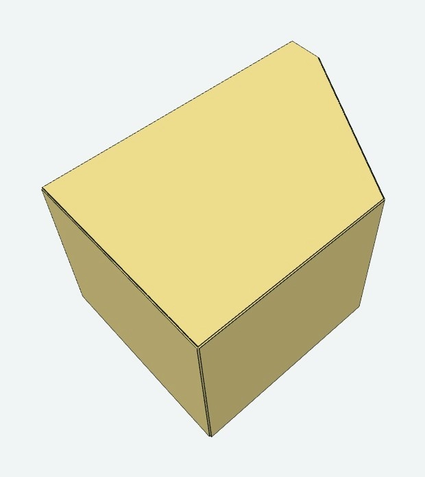
Builder checks that all 160 cells are placed and that the series chain is valid before anything is cut. Then the 3D preview shows the pack in layers: cells and busbars, the FR-4 wrap, and the metal case.
20 SERIES × 8 PARALLEL · 160 / 160 CELLS PLACED · PACK VALID · 259 × 177 MM FOOTPRINT
02 · CUT
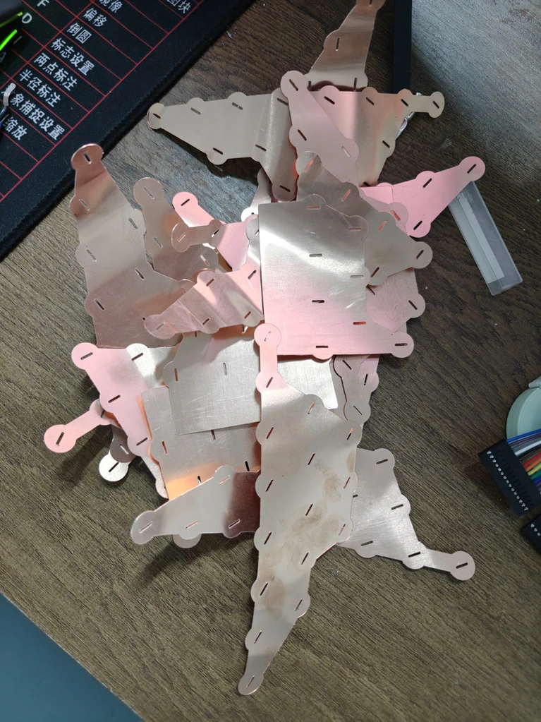
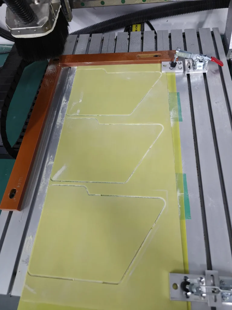
Busbars and sheets cut to the drawing
The busbars are cut to the shapes from the drawing, so each one lands on exactly the cells it’s meant to join. The FR-4 insulation sheets are cut on our CNC with the same slope as the pack.
03 · SORT & MEASURE
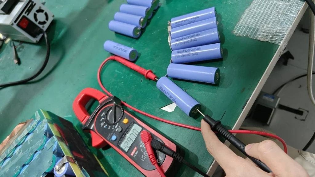
Every single cell sorted and measured
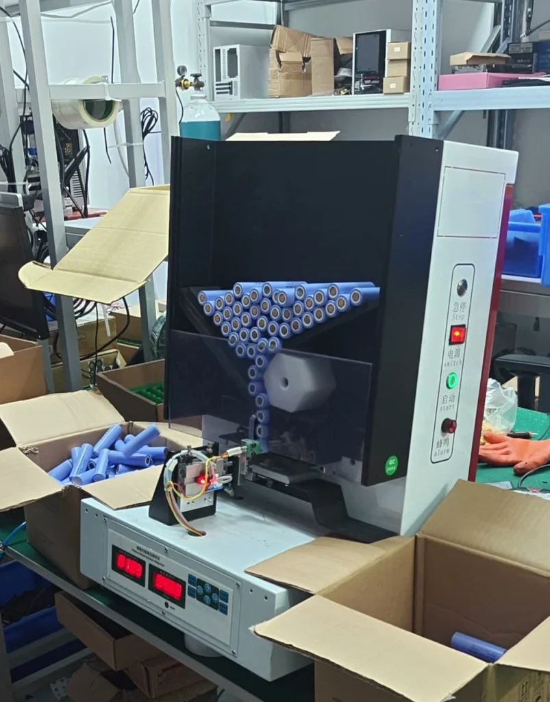
Before a cell goes anywhere near the pack, we measure it and sort it, on the tester and on our automatic cell sorter, so each group of eight is made of cells that match. It’s slow, and it’s the step most cheap packs skip.
04 · ASSEMBLE
Cells placed in their holders
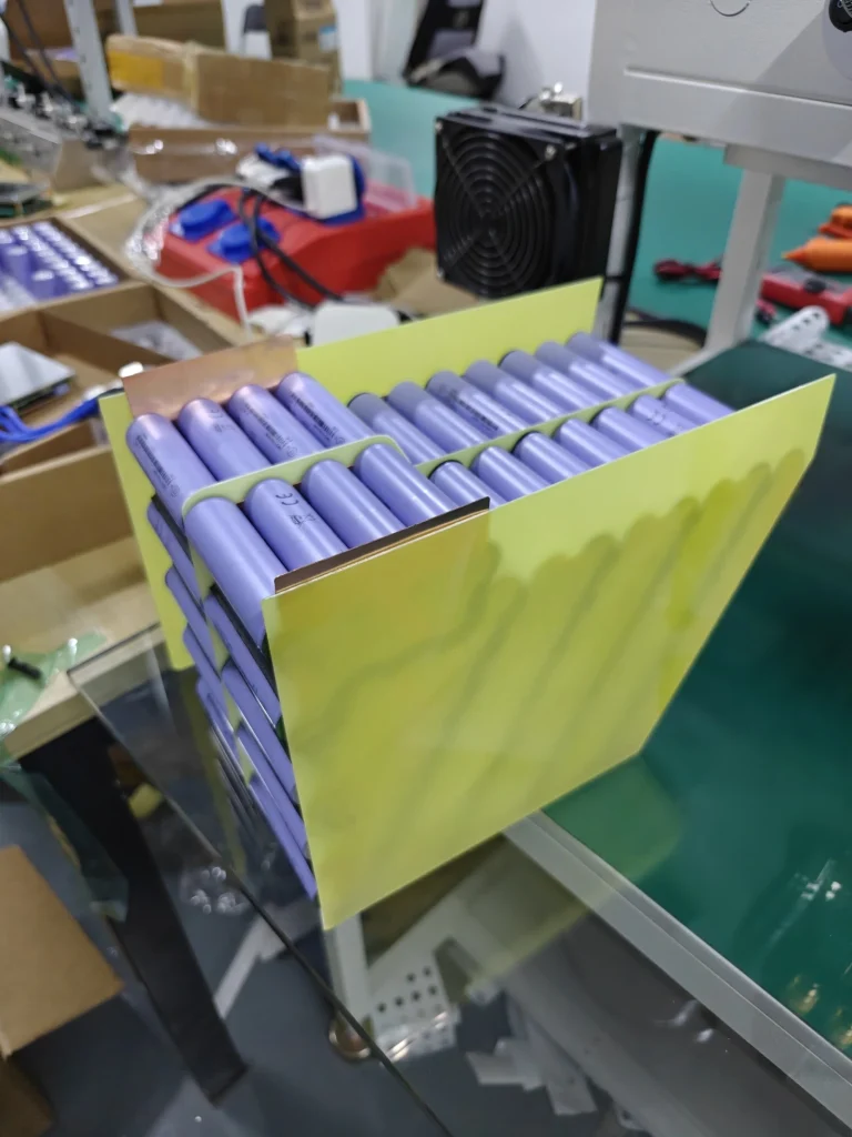
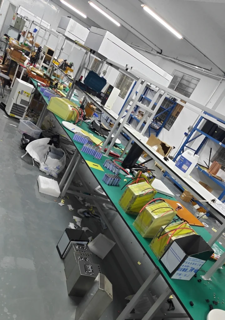
The sorted cells go into holders (we call them crates) made for this layout, row by row, so every cell sits in the spot it was drawn in. The sloped FR-4 sheet goes alongside.
05 · INSULATE
Insulation rings pasted on
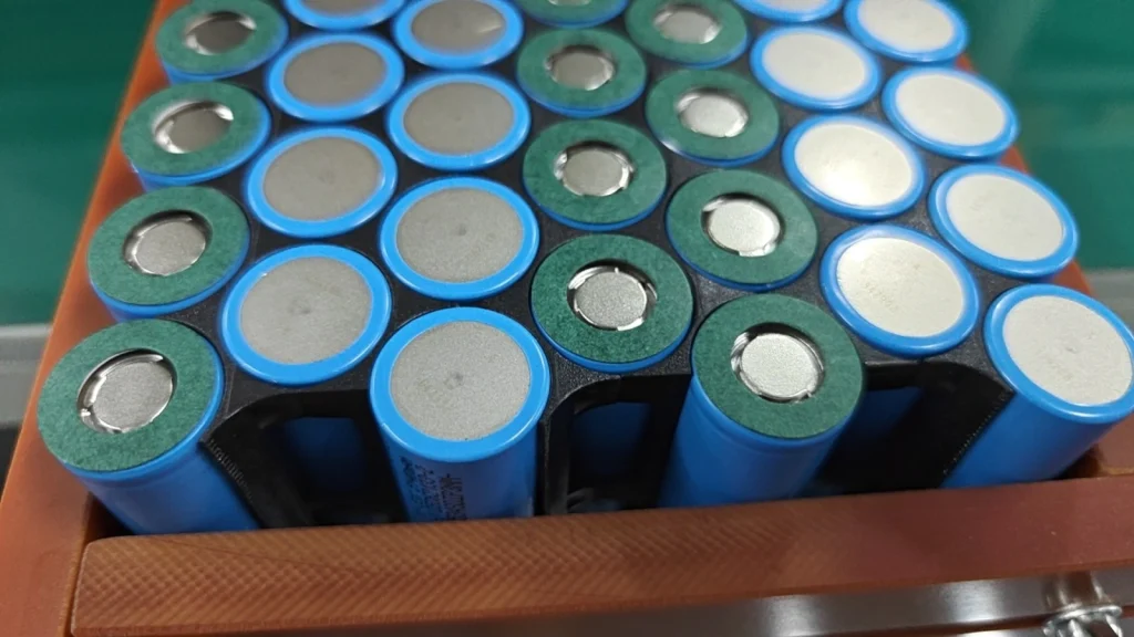
Before welding, an insulation ring is pasted onto the end of every cell. It’s a small part that’s easy to skip, and skipping it is how packs short out later.
06 · SPOT WELD
Busbars spot welded on
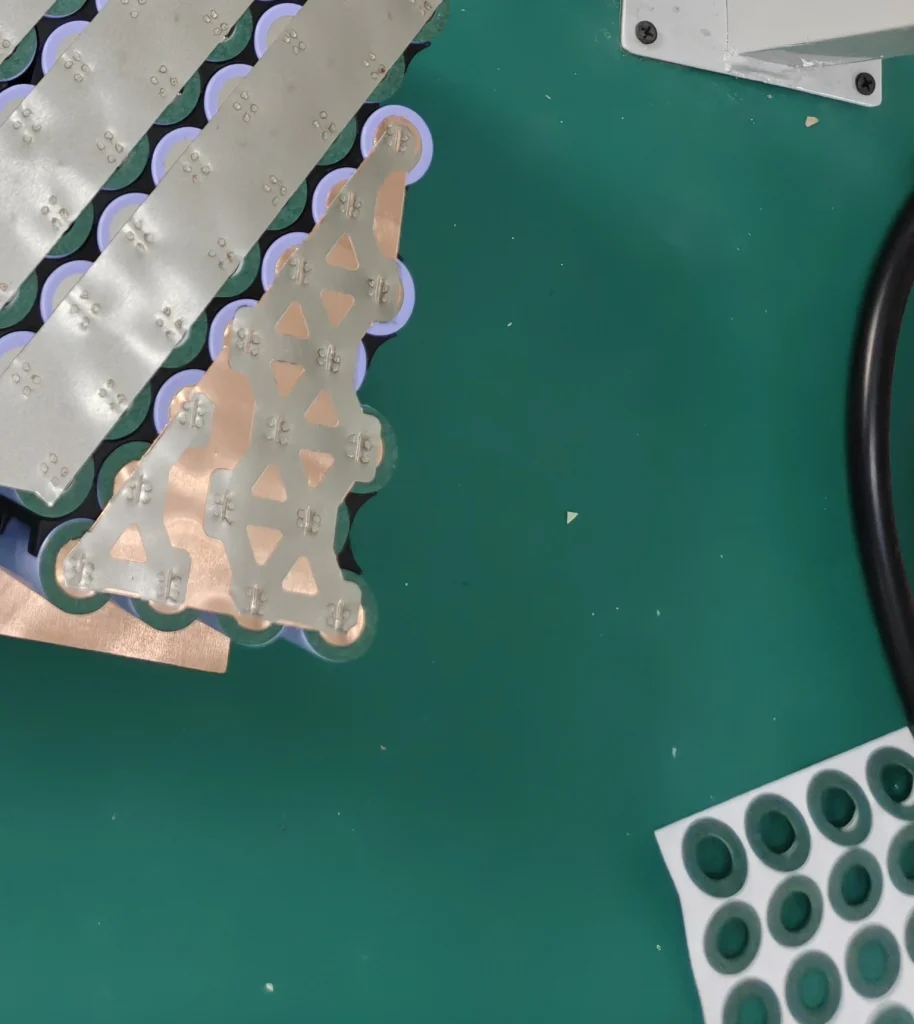
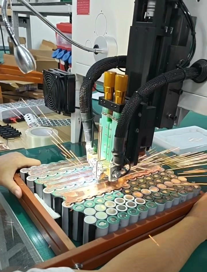
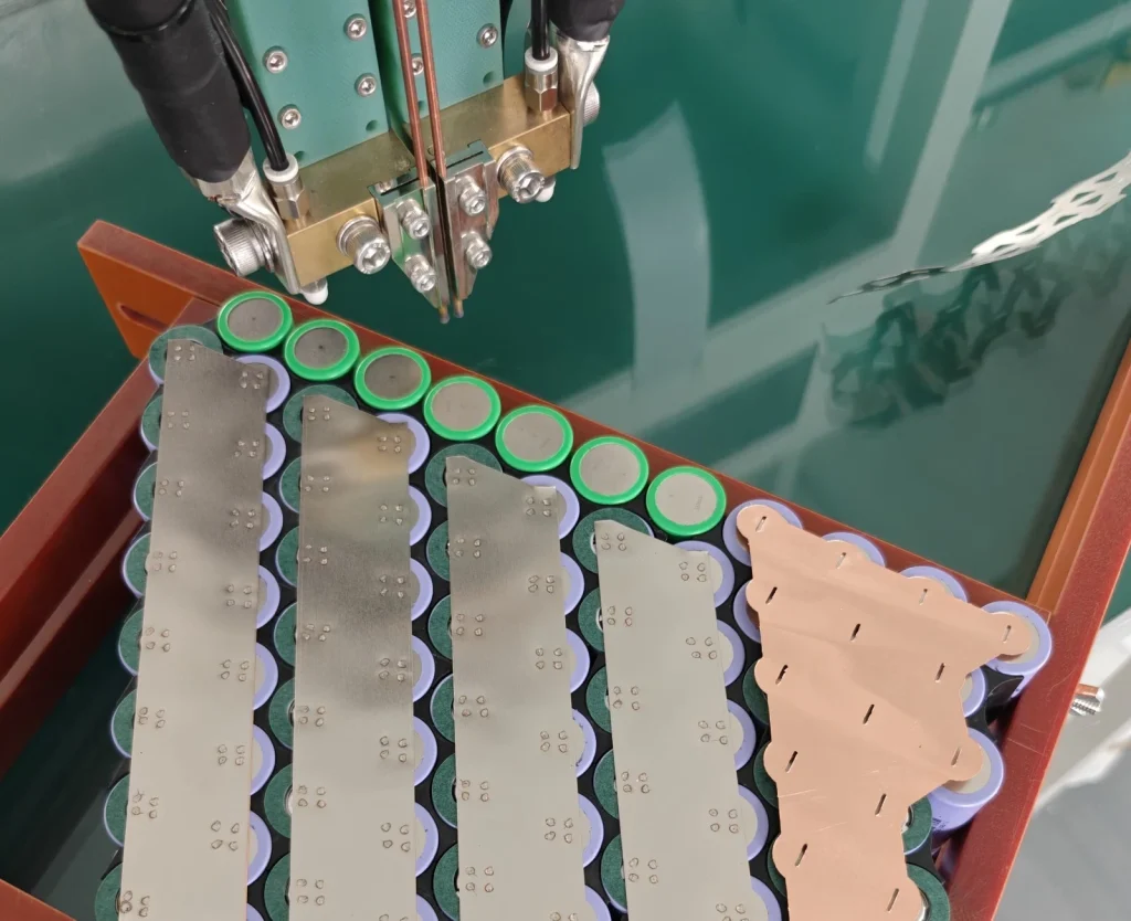
The busbars are spot welded onto the cells one by one, joining them into the 20 series groups from step one. The modules are then joined into the full pack.
07 · WIRE UP
BMS wired in
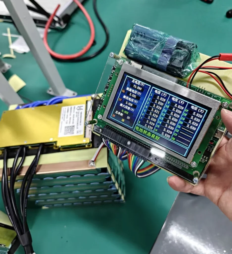
The battery management system (BMS) is mounted on the pack and wired to every series group and to the main leads. It’s what watches the cells while you ride and charge.
Then we check every series group on a cell voltage tester. On this Razor, all 20 groups read between 3.528 V and 3.531 V.
08 · WRAP & CASE
Wrapped, then cased
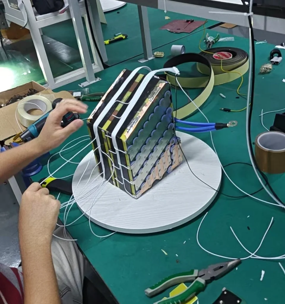
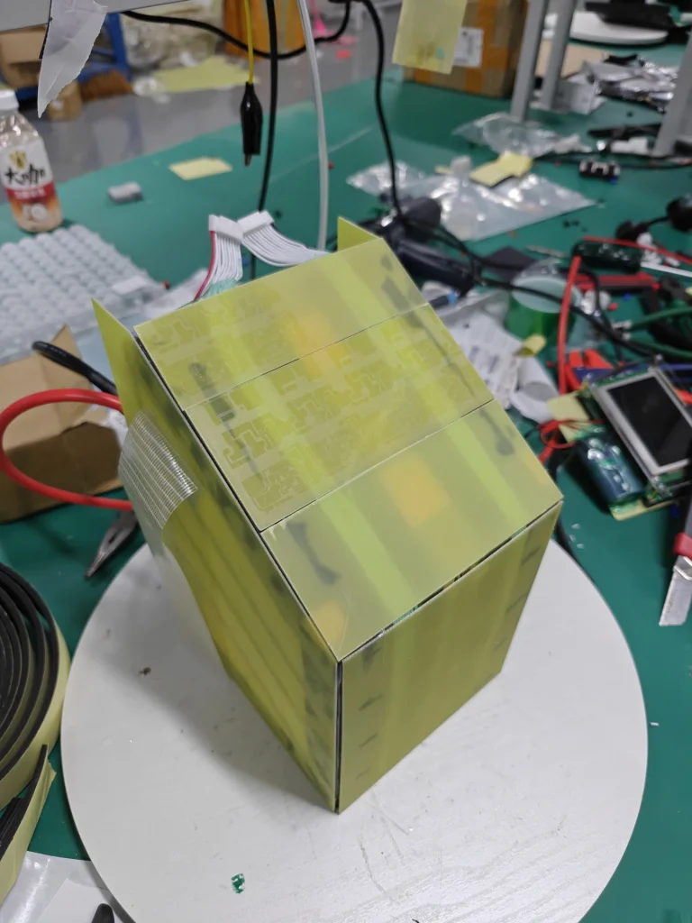
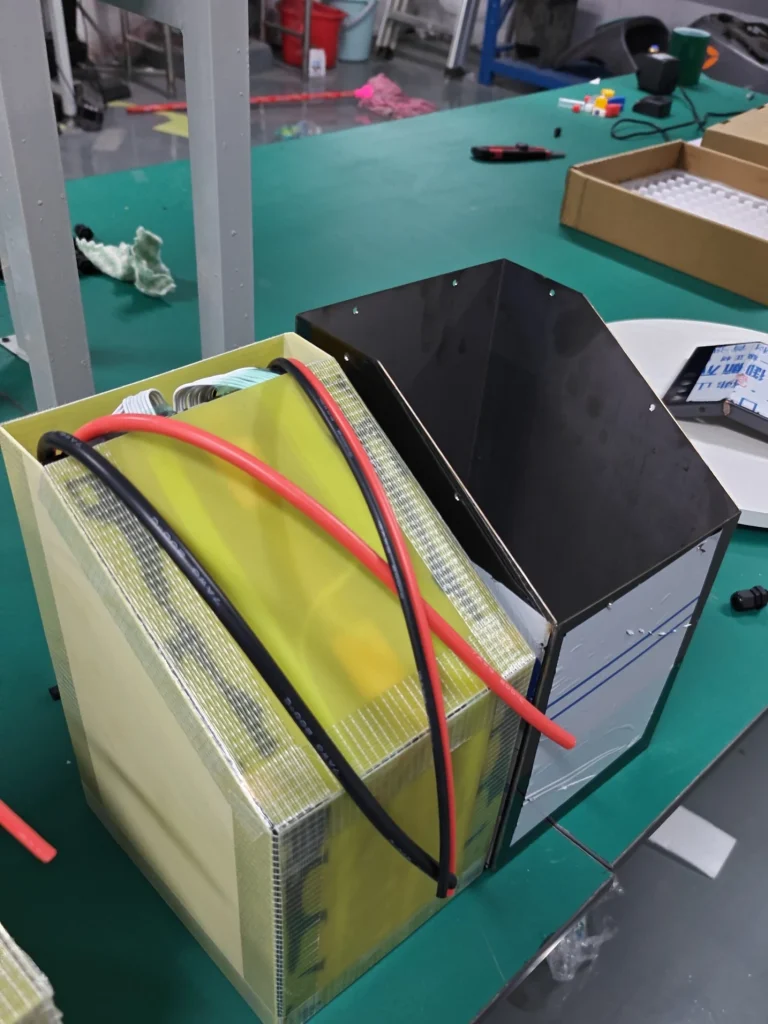
The modules are wrapped together in FR-4 insulation sheet, so nothing inside can rub or short against the case. Then the pack goes into its sheet metal case, the same one you saw in the 3D preview.
09 · LOAD TEST
Load tested before it leaves
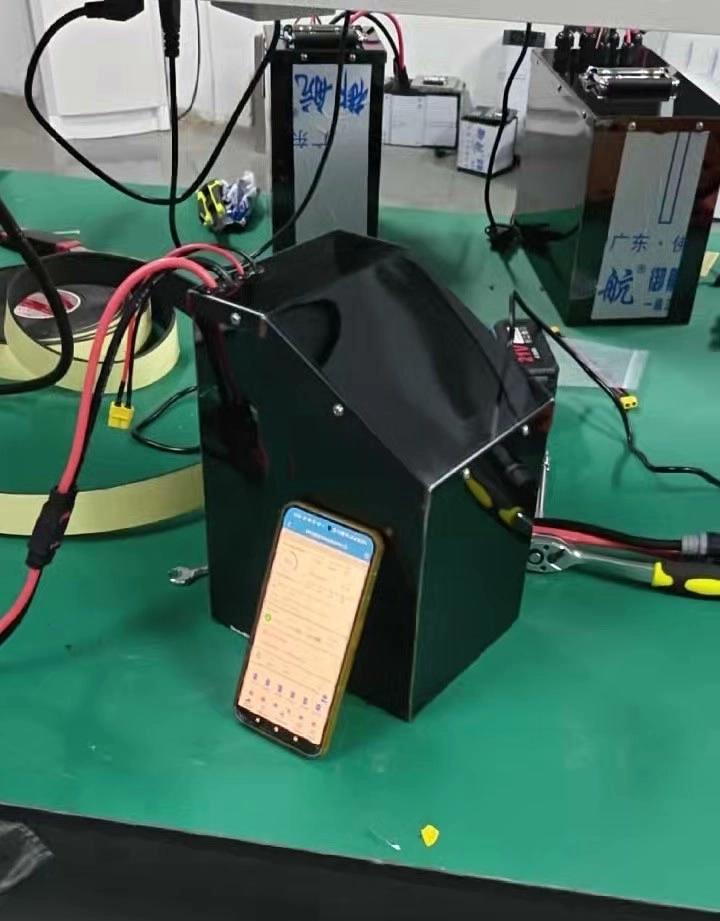
Last, the finished pack is wired to our load bank and tested, and we check the result on its BMS before it’s handed over.
FROM THE BUILD ARCHIVE
Shapes we’ve built
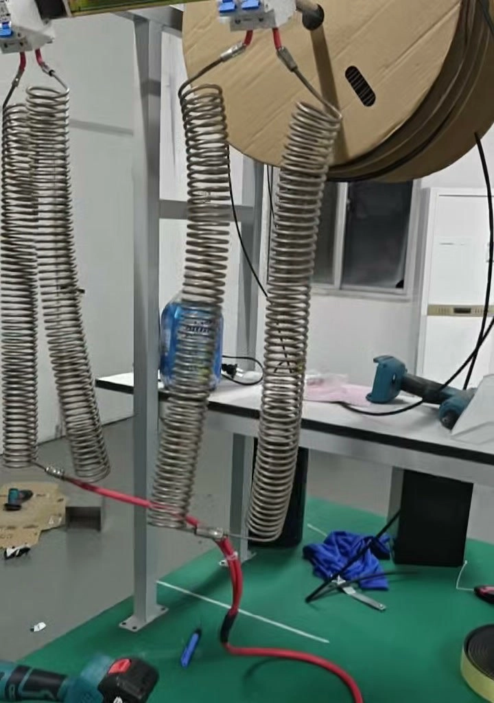
Same parts, different space. A step, a slope, a narrow bit below. See how the layout changes to fit the bike.
-
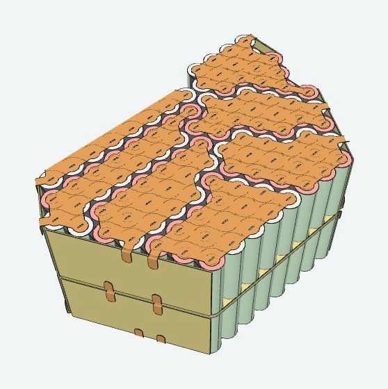
Same Fiido, two years apart
Same Fiido, same battery space, two years between builds. We built one in 2024 and another in 2026, with the same outline…
ARCHIVE BUILD · NOT A PRODUCT LISTING
Explore the build →: Same Fiido, two years apart -
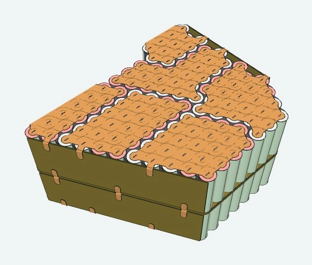
V-shaped bay, V-shaped battery
72V tells you the voltage, not whether the pack fits. This bay narrows towards the bottom, so the cell groups follow that…
ARCHIVE BUILD · NOT A PRODUCT LISTING
Explore the build →: V-shaped bay, V-shaped battery -
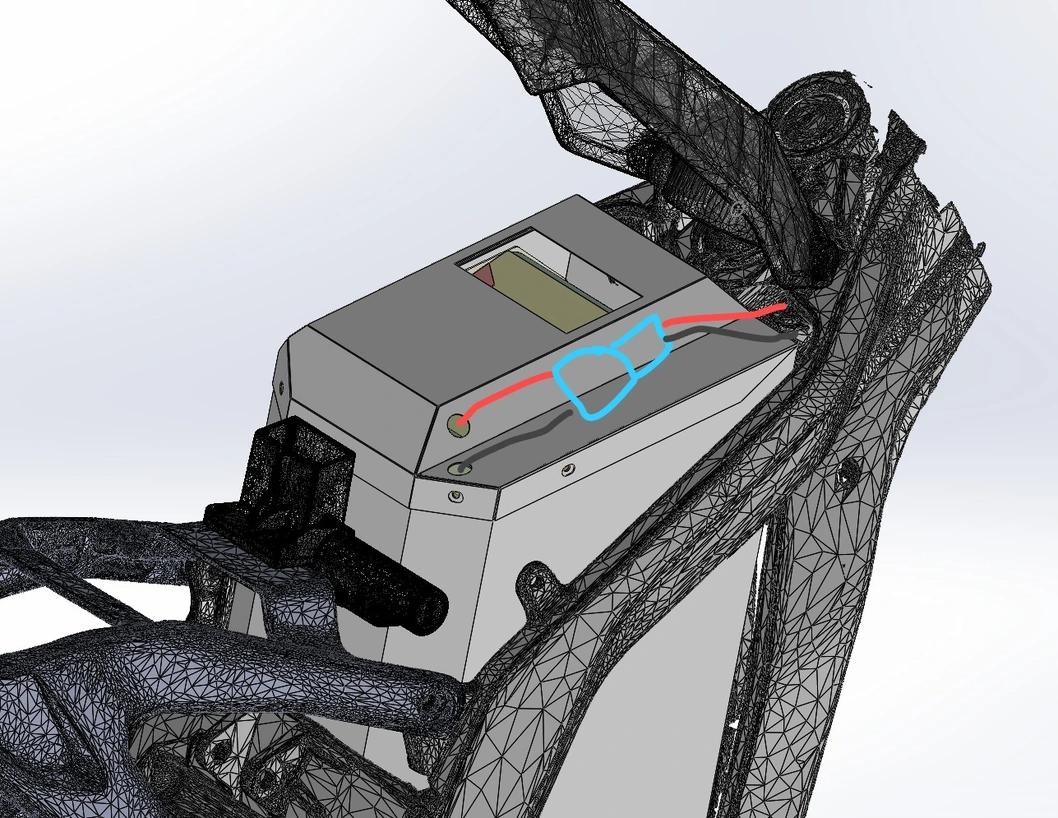
This one Light Bee, not Bubble Tea
Light Bee battery space got one funny shape, sia. We draw the frame space first, then build the pack to follow it…
ARCHIVE BUILD · NOT A PRODUCT LISTING
Explore the build →: This one Light Bee, not Bubble Tea
Awkward space or a demanding setup?
Send the usable dimensions, bike or equipment details, and whatever battery, charger and controller labels u have. We’ll talk about the whole build, not just a bigger number on the outside.